A transportation network is modeled as a network dataset by ArcGIS. With a network dataset you can find the best (shortest, fastest, cheapest …) path between locations, find the closest facilities, and determine service areas. This lab guides you through creating a network dataset and applying it to transportation problems.
So far, you have not used personal geodatabases in this class although it has most of the functions of an enterprise geodatabase. In this project, you will create a personal geodatabase and use it for transportation network analysis. By the end of the semester, you can backup your data in the SDE geodatabase into the personal geodatabase to preserve some of your work (do not do it now, your submission will be too bulky otherwise).
Do the following before you start:
-
This lab makes extensive use of the Network Analyst. The Network Analyst tools are an addon extension to
the ArcGIS toolset, and must be activated before use. NAU has a license for it, so you can go to Customize | Extensions..., and check
its checkbox.
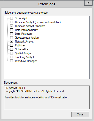
To enable the toolbar in ArcMap, just go to Customize and it should be there. For ArcCatalog, however, you'll have to create a new toolbar and manually drag the Network Analyst tools onto it.
- Use ArcCatalog to create a personal geodatabase named FLGjb3379 on your X drive (or wherever you want)
- Import (drag and drop) your Transportation feature dataset (including its contents) from the SDE geodatabase into your new personal geodatabase
-
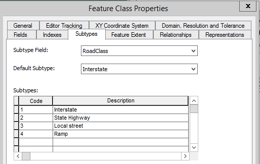
Check if the subtypes of the Streets feature class are properly imported into your personal geodatabase by right-clicking on it,
choosing properties, and clicking the Subtypes tab. There should be 4, just like in the feature class on the server. If not, refer to
Lab 3 to recreate them.
-
Part One: Creating a Network Dataset

Creating a new network dataset is not difficult, though setting up a good network dataset later may take tremendous amount of time and patience.
- In ArcCatalog, open your FLGjb3379 geodatabase.
- Right click on your Transportation feature dataset and choose New | Network Dataset.
- Enter the name TransportNet for your new network dataset, and click Next.
- Check the Streets checkbox, leave the version at the default, and click Next.
- At the Do you want to model turns? question, click Yes if it isn't chosen already, and Click Next.
-
Click the Connectivity button to set up network connectivity. In the connectivity dialog:
- Click the Subtypes button, and ensure that all subtypes of the Streets feature class are there. There should be 4. If so, check the checkbox and Click OK. The four subtypes should appear in the list. Note that there are certain cases when not all subtypes will be shown here.
- The Connectivity policy End point will be automatically applied to all subtypes. Change the policy of the State Highway and Local Street subtypes to Any vertex. This allows state highway and local street segments to be connected at coinciding vertices and end points/nodes.
- Leave the others at their defaults, and click OK to get back to creating New Network Dataset wizard.
- Click Next.
- At the How would you like to model the elevation of your network features? question, choose None, and click Next.
-
Specify the attribute for the network dataset. Two attributes, Minutes and One-way, are
automatically added to the new network dataset because the names exist in the Street feature class. If you do not see the
Length attribute, click the Add button to add it:

-
If you have created the Length attribute, it is added to the attribute list, but it may be marked with an exclamation sign indicating
that it is not evaluated. Even if it is not marked, continue anyway:

- Double click the Length attribute (or select it and click the Evaluators button) to evaluate it.
-
Follow the example in the screenshot below to set the from-to and to-from edge element values. This
step sets the shape length value of each street segment as a cost for both from-to and to-from direction. Click OK. If the exclamation
point was present, it should disappear:

- Click Next.
- You will see the travel mode setup page. Click the plus sign next to the travel model box to create a name "Driving", then all the other fields in this dialog will be automatically filled as the following. (If you wish, you could create a different travel mode for the network)
- At the Do you want to establish driving directions settings for the network dataset? question, choose Yes, and click the Directions... button.
- In the General tab, set the street name fields as follows, and click OK.
(This step specifies how streets will be describes in trip directions) - Click OK, then click Next.
- If the Do you want to specify a configuration keyword? question appears, choose Yes and accept the NETWORK_DEFAULTS configuration keyword, then click Next. If it doesn't, continue.
-
Review the summary and click Finish. ArcGIS will create the new network dataset. At the Would you like to build it now? question, click
Yes. After it compltes, you should now have a working network dataset.
- Close ArcCatalog, and Open ArcMap.
- Ensure that the Network Analyst toolbar is enabled.
- Add your TransportNet network dataset, with all participating feature classes, into the map.
On the Network Analyst toolbar, your TransportNet network is automatically selected in the toolbar.

- To find the shortest path, click Network Analyst | New Route. A new route layer is added to the contents frame.
- Use the Create Network Location tool and place two points in the downtown area.
- Click the Solve button.
-
The result is very inaccurate. This is because the network dataset attribute Minute (travel time) is used as a default cost in
finding the shortest path. Since the Minutes field of your streets feature class contains only zeros, ArcGIS cannot give an accurate
path with this attribute. Before fixing the Minutes values, however, you can do this to find the shortest path between the two locations:
- In the Table of Contents, click the List By Drawing Order button.
- Right click on Route and click Properties.
- Click the Analysis Settings tab.
- Change the Impedance from Minutes to Length, and click OK.
- Click the Solve button.
The path now must make a lot more sense.
-
Now, use the following procedure to fix values for the Minutes field:
- In the Table of Contents, right click on the Streets layer | Edit Features | Start Editing. It will give a warning that says the layer can't be edited, ignore it and click Continue.
- Open the attribute table of the Streets feature class.
- Find the Minutes field and click on the column header to highlight the entire column.
- Right click on the header of the Minutes field, select Field Calculator.
- In the Field Calculator dialog, enter
[SHAPE.LENG] / ( [SPEED] * 88)in the lower box. - Click OK to calculate. It shouldn't take too long. Once it completes, close the table, save edits and stop editing.
- Click the Build Network Dataset tool on the Network Analyst toolbar to rebuild the network. If it says that there is already a lock and can't do it, it's because you have ArcCatalog open. Close both ArcMap and ArcCatalog, reopen the map, and try again. It shouldn't take too long to rebuild.
Now, try to use Minutes as an impedance when repeating step 26. Solve should work now.


- In ArcCatalog, open your FLGjb3379 geodatabase.
-
Part Two: Setting Up On-way Streets
So far the Oneway field of your Streets feature class is still blank, so your network dataset still does not handle one-way traffic. The consequence could be disastrous if you use it to guide driving, because people might be directed to drive against traffic on the highway.
In this part of the lab, you will assign values to the Oneway field of all interstate highways and ramps and some streets in the downtown area. Refer to the following three maps for one-way directions. For the highway segments it's recommended that you work sequentially by starting from the east or west end of I-40. Do not miss a segment, or you'll be in trouble.


Use the following steps to assign one-way values:
- Start ArcMap and add your TransportNet with all its participating feature classes into the map, if you're starting fresh.
- In the Table of Contents, right click on the Streets layer | Edit Features | Start Editing. It will give a warning that says the layer can't be edited, ignore it and click Continue.
-
Use the Edit Tool
 to select a road segment, then click
on the Edit Vertices tool
to select a road segment, then click
on the Edit Vertices tool  to see all the vertices and
nodes of it. The little red square indicates the end node, and therefore the direction of the segment.
to see all the vertices and
nodes of it. The little red square indicates the end node, and therefore the direction of the segment.
If the one-way traffic direction follows the physical direction of the line, assign FLW to the Oneway attribute by using the Attributes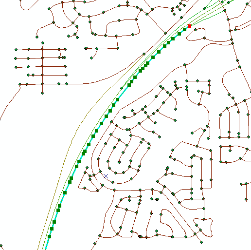
 tool on the Editor toolbar; otherwise assign AGS (indicating against) to it. Values FLW and AGS are arbitrary labels used to
distinguish directions - if you wanted to, you could use other labels.
tool on the Editor toolbar; otherwise assign AGS (indicating against) to it. Values FLW and AGS are arbitrary labels used to
distinguish directions - if you wanted to, you could use other labels.
Ordinarily, one-way traffic has to be manually assigned feature by feature. However, fortunately for us all expressways and ramps in the Flagstaff streets feature class have been digitized following traffic directions, thanks to the GIS experts who created the data set. Thus, you can select all expressway and ramp segments and assign FLW to the Oneway attribute all at once by using the field calculator.
- For the local one way streets, you have to assign the labels manually.
-
Once all the street segments have been edited, Save edits and stop editing. Now the Oneway field of your Streets feature class has values.
-
However, the network dataset is still not aware of your work. You need to evaluate the Oneway attribute of your
TransportNet network with the values you entered, and rebuild the network.
NOTE ...Because of a bug in the ArcGIS software, you CANNOT complete this step on a network. The Access database MUST be on a local drive, or ArcMap will give an error that says it can't get a schema lock. After this step is complete, you can move the modified database back to its original location.- In ArcMap, open the ArcCatalog window, and right click on your TransportNet network. Choose Build. Then, choose Properties.
-
Select the Attributes tab, then double click on Oneway.

- In the Evaluators window, double-click the From-To item. The Field Evaluator dialog box opens.
-
Copy and paste the VBscript below directly into the box. Click OK after pasting.
If UCase([Oneway]) = "AGS" Then
  restricted = True
Else
  restricted = False
End If
-
Back in the Evaluators window, select the To-From item and click the
Evaluator Properties button. This time, copy and paste the following code into the script box:
If UCase([Oneway]) = "FLW" Then restricted = True Else restricted = False End If - Click OK and OK to finish updating network dataset attributes.
- Right click your TransportNet network and choose Build again. Whenever you change settings of a network dataset, you have to rebuild it.
-
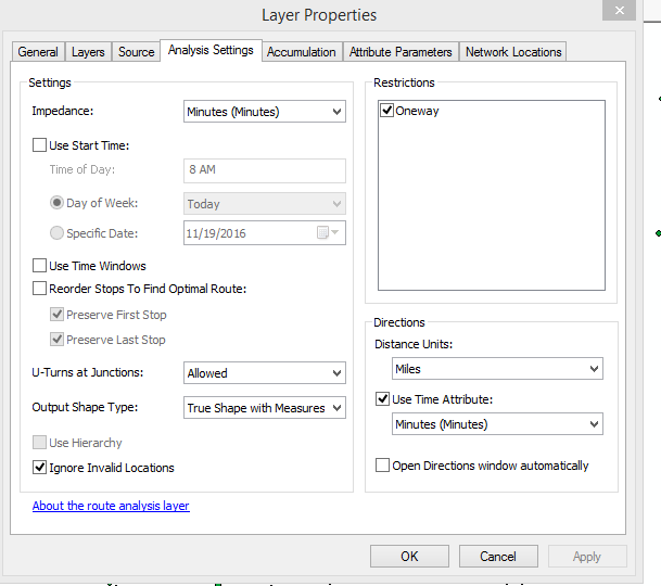
After rebuilding, right click on the route layer, choose Properties, then choose the Analysis Settings tab.
Make sure that the Oneway restriction is checked, and the route impedance
is set to Minutes (Minutes).
In addition to creating locations by using tools on the network analyst toolbar, you can use your address locator from the previous lab to set locations in path finding. For example, to find the best route from "888 W Lone Star Trl" to "4450 N Randall St" you can interactively geocode the addresses. (You may need to create a new address locator in your personal geodatabase if the SDE address locator is not available.) When you see a matched address in the lower box as shown in the snapshot below, right click on it and select Add as Network Analysis Object to add it to the network.

You may be surprised by the great details and accuracy of the route, especially how it gets on and off the interstate highways.
Create a map of this trip for submission.
- Start ArcMap and add your TransportNet with all its participating feature classes into the map, if you're starting fresh.
-
Part Three: Setting Up Turns
Every street junction has as many as n2 possible turns. Each turn may have a different impedance or cost which is usually measured by time, in minutes, for making the turn. At the same street intersection, making a left turn usually takes more time than making a right turn. Straight transition usually takes the least time. You can restrict a turn by assigning a negative turn cost (e.g. -1) to it.
In a geodatabase, turns are maintained in turn feature classes. In this part of the lab, you will create a turn feature class in the Transportation feature dataset using ArcCatalog; then you will create turns in the turn feature class by using ArcMap.
Follow the steps below to create a new turn feature class named Flag_Turns:
-
In ArcCatalog, check Customize | Extensions... to make sure that the Network Analyst has been checked, then right click on your Transportation feature dataset, and select New | Feature class.
-
In the subsequent New Feature Class dialog:
- Enter name: Flag_Turns. Alias: Flagstaff Turn Features.
-
Select Turn Features in the type of features drop-down list. Your network dataset will be automatically selected in the next
combo box.
Leave 5 in the maximum number of edges per turn. This means that a multi-edge turn you may create later can traverse up to 5 edges. Most turns
involve only two edges, a few turns in this lab will need three or four edges.

- Click Next.
- Add a new field named Minutes with Double data type to the end of the field table.
- Click Finish, and close ArcCatalog.
-
Next, you will add turns to the four street intersections on Route 66 (not Santa Fe Ave or S Milton Rd) in the downtown area as shown in the map below. As you add the turns (explained later):
- Pay attention to the one-way streets (indicated by green arrows) when you create turns. To restrict certain turns you can assign negative values (-1) to the Minutes field.
- Create multi-edge (3- or 4- edge) turns for the intersections marked by the larger circles.
- The two short green arrows in the large circle indicate that only the two short segments are one-way streets.
- You do not need to create U-turns and straight transitions at the intersections.
-
Use your experience to estimate times for making left and right turns at different locations. The following table provides a quick look-up between seconds
and minutes.
Seconds 5 10 15 20 25 30 40 60 Minutes 0.08 0.17 0.25 0.33 0.42 0.50 0.67 1.00 
-
To add the turn features to the 4 intersections:
- Start ArcMap. If you are using an existing map from parts 1 and 2, you have to delete the layers and then add your TransportNet network with all participants into the map again, so that your Flag_Turns layer will show up.
- Start a Streets editing session, ignoring the error.
- Select Edge Snapping in the snapping toolbar. Later, you may get errors with just this snapping on; try adding Vertex Snapping too.
- Zoom in to an intersection.
- Select the Create Features tool on the Editor toolbar, then highlight the Flag_Turns feature class in the create feature window, if it isn't already.
- To create a turn, sequentially click on each edge that a turn needs to traverse, then double click on the last edge to end it.
- Click the Attribute tool on the Editor toolbar to set a value for the Minutes attribute.
- After the four turns are complete, save and stop editing.
- Click the Build Entire Network Dataset tool on the Network Analyst toolbar to rebuild the network.

Find a route that takes some of the turns.
-
In ArcCatalog, check Customize | Extensions... to make sure that the Network Analyst has been checked, then right click on your Transportation feature dataset, and select New | Feature class.
-
Part Four: Applications for Submittal
Application 1: Best path
Peter is going to deliver books to elementary schools of the Flagstaff Unified School District (FUSD). He has a list of 12 school names with addresses (a text file named Schools.txt on the
Rdrive). You will help Peter to find the best delivery route.This is the general procedure:
- Load the text file and your TransportNet into ArcMap.
-
Geocode the schools by using the addresses in the Schools table that you created in an earlier lab or by using Dr.
Huang's Online Geocoder EXE (see below), and save the result as a point feature class named Schools in the Administrative feature dataset. Note that if you use the geocoder that you created, one school may not be geocoded because the reference map does not have
house numbers for some streets. To fix it, use the Google map to find the school location, then manually match it in the Rematch window, like you
did in the previous lab.
Using Dr. Huang's Online Geocoder
- If you haven't already, go get Dr. Huang's Online Geocoder EXE from Slide 24 (last slide) of lecture 9.
- Bring Schools.[txt | csv] into Notepad, and split the Name and Address fields, if they aren't split already.
- Run the Geocoder EXE and import the .TXT or .CSV file.
- Geocode it, and save the results as a new text file in the same folder, suggestion could be Schools_Geocoded.[txt | csv].
- Open the result in Notepad and inspect it for errors. Make sure that the Latitude and Longitude column header names are not backwards. If it's OK or after correcting errors, close Notepad.
- Open ArcCatalog, and make sure that the analyst licenses are checked.
- Right-click on the text file and choose Create Feature Class... | From XY Table...
- This next dialog box is a key part of the procedure. Choose the appropriate Geographic Coordinate System (in this case I picked WGS 1984) for the Coordinate System of Input Coordinates... button. Save the output into your personal geodatabase as a feature class called Schools in the Administrative feature dataset. In the Advanced Geometry Options... button, the Use a Different Spatial Reference... radio button should be chosen, and the Projected Coordinate System that we're using in this lab (Arizona FIPS 0202) should be chosen.
- When you click OK, in a couple of seconds the geocoded Schools feature class should appear in Administrative feature dataset. If you add it to the map it should look OK.
-
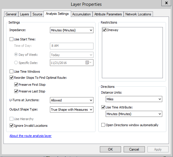
Create a new route layer and open its Layer Properties to configure Analysis Settings:
- Ensure that the Oneway restriction is checked.
-
Check the Recorder stops to Find Optimal Routes, with the following also checked:
- Preserve First Stop
- Preserve Last Stop
- Uncheck Use Time Windows, if it isn't already.
- Click OK.
- On the Network Analyst toolbar, open the Network Analyst Window
 .
. - Right click on Stops and select Load Locations... Your Schools feature class should be selected, and the tolerances are OK for now. Click OK. Once loaded, expand the Stops to see all the school addresses. The schools on the map should have little numbers on them as well.
- Drag the Sechrist Elementary School item to the top, and the South Beaver Elementary School item to the end of the list, so that the trip will start and end with these two schools, and click Solve.
Create a color map to show the route.
Application 2: Closest Facility
Mary is a new graduate student of NAU. She has found an apartment at 428 E David Dr. You will help Mary find the closest school for her six year old child.
This is the general procedure:
- On the Network Analyst toolbar, create a new closest facility layer.
- Inspect the layer properties, especially the Analysis settings. If everything looks good, click OK.
- In the Network Analyst Window, if your closest facility layer is selected in the TOC, it will be selected in the window.
- Right click Facilities and choose Load Locations. Load the Schools feature class.
- Right click on Incidents and select Find Address...
- Enter Mary’s address, 428 E David Dr, as an incident location. Click Find.
- Right click the result, and choose Add as network analysis object. Mary's address will appear in the Network Analyst Window.
- Close the Find dialog box, and click Solve.
Create a color map to show the route.
Application 3: Service Area
Sam opened a new Sandwich shop at 218 S Beaver St. He knows that his customers are mostly within ten minutes walking distance (about ½ miles, or 2640 ft) from his shop. He is looking for a student who can use GIS to determine a service area so he will distribute flyers. In exchange for the GIS work, Sam promises you free lunch for a week.
This is the general procedure:
- On the Network Analyst toolbar, create a new service area layer.
-
In the layer properties, Analysis settings, set the following:
- Impedance to Length
- Default Breaks box to 2640 (half a mile)
- In the Network Analyst Window, right click on Facilities to geocode the shop address and add it as a network analysis object, like you did in Application 2.
- Click Solve.
Create a color map to show the service area.
Create the FLGxxx.zip file from your personal geodatabase for submittal.