Before starting this lab, ensure that your water_line subtype data is as follows (ArcCatalog | Your Geodatabase | Utilities | Water_line | Properties | Subtypes). It should be if you haven't touched it since lab 5 or so:
| Code(Pipe_funct) | Description | Pipesize default | Pipe_type default |
|---|---|---|---|
| 10 | Transmission | 30 | 16 |
| 20 | Water main | 12 | 20 |
| 30 | Fire lateral | 4 | 20 |
| 33 | Service lateral | 2 | 15 |
The water supply to the new development is designed as part of the final plat of parcel 105-12-001B (the plat you worked on in the last lab). Water mains will be extended from the existing one at the entrance of the development and be laid along the streets in the new community.
-
Part One - Water supply design for final plat
-
Create a new geometric network in ArcCatalog:
- Right click the Utilities feature dataset | New | Geometric Network.
- Read message on the first page of the wizard, click Next.
- Enter a name for your geometric network: Utilities_Net. Snap feature within specified tolerance: Yes, 1.0 foot. Click Next.
- Select feature classes you want to build your network from: Water_line, Water_junctions, and Fire_hydrants. Click Next.
-
Select roles for the network feature classes and click Next:

-
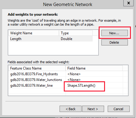
Add weights to the network:
- Click the New button to create a new weight named Length of Double data type. Click OK.
-
In the lower box, select the Shape.STLength() field of the water line feature class. This step creates a new weight for the network named Length and associates it with the length attribute of the Water_line feature class. Click Next.
- Choose No at the do you need to specify a configuration keyword prompt, and click Next.
-
Read summary of your input, and click Finish. It'll take awhile to create your network.
Name: Utilities_Net
Snap Features: Yes
XY Cluster Tolerance: 1 Feet

Feature Classes:
  gdb2016.JB3379.Fire_Hydrants
  gdb2016.JB3379.Water_Junctions
  gdb2016.JB3379.Water_line

Feature Class Roles:
  Simple Junction:
    gdb2016.JB3379.Fire_Hydrants
    gdb2016.JB3379.Water_Junctions
  Simple Edge:
    gdb2016.JB3379.Water_line

Feature classes that contain sources or sinks:
  gdb2016.JB3379.Water_Junctions

Weights & Associated Fields:
  Length :: Double
    gdb2016.JB3379.Water_line.Shape.STLength()
-
Add new features to your utility network:
- In ArcCatalog, register your Utilities feature dataset as versioned. It may say it can't be versioned, but ignore it and let it take awhile, it will do it. After it's done check it then close ArcCatalog.
- Open ArcMap, click the Catalog button and check to see if your geodatabase connection is active. If not, connect.
- In ArcMap add your Utilities_Net to the map. The geometric network and all participating feature classes are added to the map.
- Add the Water_Valves and Parcel feature classes to the map, if they aren't already there.
- Switch to your Final Plat version.
- Start an editing session.
-
Enable End Snapping and Edge Snapping in the snapping toolbar, then check Snap To Sketch under the Snapping menu.

-
In the Create Feature panel (click the Create Feature tool
 on the Editor
toolbar if the panel is not visible), highlight the
on the Editor
toolbar if the panel is not visible), highlight the
Water main subtype of the Water_line feature class to set the subtype as editing target. -
Use the Straight Segment tool to digitize a new water main. Start by snapping to the end point of the existing water main at the entrance of
the new neighborhood, then digitize a new water main by following the new street centerlines, and end by snapping to your sketch at the T street
intersection.
-
Check attributes of the newly created water main by using the Attributes tool
 on the editor toolbar. Make sure you use the following specifications for
the new water main:
on the editor toolbar. Make sure you use the following specifications for
the new water main:
- Pipe_funct: Water main
- Pipesize: 10 (note that at the beginning of the lab you checked the value of this subtype, it was 12 - change it to 10)
- Pipe_type: 20
Note that since you have created subtypes for water lines and assigned a default values to each subtype, you can simply select values.
-
Change your editing target to subtype Fire lateral so that you can add new fire laterals. Use the Straight Segment tool to create six fire laterals
as shown in the figure below. Notice the green lines. This is how long you need to make them:
- Zoom into the street width to allow reasonable accuracy in digitizing
- Make sure your new fire laterals are snapped to the water main.
- Note that once you have added a new edge, junctions are automatically created because you are editing a geometric network
- Check fire lateral parameters: size: 4", type 15 (default type is 20).
-
Change your editing target to feature class Water_valves to add a valve to each fire lateral.
- You need to zoom in enough times for accurate editing.
- Be sure your valves are snapped to pipes.
- Change editing target to feature class Fire_hydrants to add a hydrant to the end of each fire lateral.
- Save your edits and stop editing.

Note: You are not required to use professional utility symbols while editing map layers, but...it sure helps! Notice how I used different symbols in the map above.
-
Create a new geometric network in ArcCatalog:
-
Part Two - Water flow analysis in geometric networks
To determine flow direction in a geometric network, you need to specify sources and sinks first. For the Ponderosa Trail area, since water flow direction in the transmission main is from north to south, let’s assign a source to the water junction at the northeast corner (HMID = 15641).
To specify a source in this network:
- In ArcMap, make sure your version is the Final Plat, and open the map you have been using for this series of labs..
- Start an editing session.
- Change the target layer to Water_junctions.
-
Switch to the Edit tool (
 ), then use Select By Attributes to
select the junction (HMID = 15641). Then zoom to the selection.
), then use Select By Attributes to
select the junction (HMID = 15641). Then zoom to the selection. -
Click the Attributes tool on the editor toolbar to open the
attribute window.
- In the attribute window, change the value of AncillaryRole attribute to Source.
-
Bring up the Utility Network Analyst toolbar if it isn't showing already.

-
Click Flow | Display Arrows on the utility network analyst toolbar. You may see that all the water line segments are marked as uninitialized; don't worry, it's because flow has not
yet been computed. To compute the flow; click the Set Flow Direction button
 . Arrows and black dots will appear
in the map, indicating different flow states.
. Arrows and black dots will appear
in the map, indicating different flow states. 
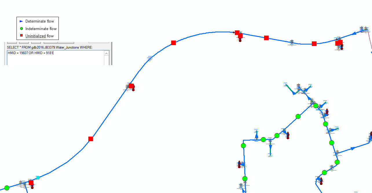
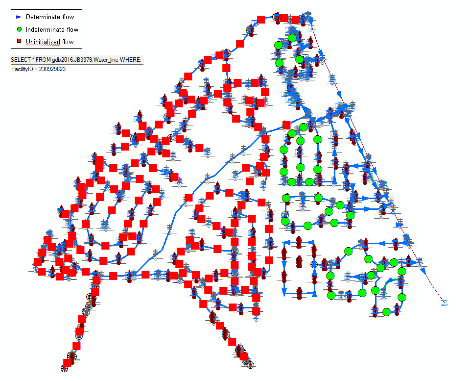
- To help interpret results and for cartographic asthetics, you need to customize the flow symbols. To do so, click on the Flow | Properties, then in the Arrow Symbol tab page, change your flow symbols to those shown in the map above. The map uses a size 12 blue arrow for determined flow, a size 10 green circle for indeterminate flow, and a size 10 red square for uninitialized flow. Note that ArcSDE does not save your flow symbol preferences in the geodatabase, they are saved in the map document. If you turn off display of the junctions, valves, and fire hydrants, your map should look similar to the snapshot above, without the legend.
-
The widespread indeterminate flow symbols are due to loops in the geometric network. Determining flows in such loop circuits would require very complex hydraulic models which
take into account a wide range of factors such as the size, length, material of pipes, the shape of junctions and valves,
topography (elevation, slope) on which pipelines are laid, as well as the water use conditions (on/off of faucets). Fortunately, complex calculations like that are beyond the
scope of this course and the ArcGIS software, so you do not need to worry about those indeterminate flow symbols. Remember, there are water flows in
indeterminate flow direction segments.
What you do need to pay attention to for this lab are the uninitialized flows, because they indicate isolated sub-networks, where there may not be water flows in those pipes. Our new development area is in one of those isolated subnets. Isolation of subnets may be caused by the following errors:
- Part of the network is graphically disconnected from the main network
- Part of the network is topologically disconnected from the main network though it is graphically connected.
-
If you zoom into the subnet that includes our new development, you will find that this subnet is graphically disconnected from the 30" transmission pipe
on Lake Mary road. This subnet may be fed by another source outside the map extent.
To establish water flows in this subnet, you set the value of AncillaryRole of water junction (HMID = 4195), located at the northeastern corner of the subnet, to Source, then click the Set Flow Direction button again. You will find that uninitialized flow symbols in the subnet are replaced by determinate or indeterminate flow symbols. -
The second type of error (topologically disconnected subnet) has caused two isolated subnets in the southwestern corner of the map.
To fix these topologically disconnected errors, you use the Geometric Network Editing tool to manually connect the isolated subnet
to the main network topologically. To do so:
-
Bring up the Geometric Network Editing toolbar if it isn't already.

-
Use the Edit Tool to select the water line segments in the isolated subnet that should have been topologically connected to the
main network. Hold the Shift key to select multiple features if necessary, as shown below.

- Click the Connect button
 .
. -
Click Set Flow Direction to recompute the flow again. Once detached subnets are connected, and the
section of map shown above should now look like this:

-
Bring up the Geometric Network Editing toolbar if it isn't already.
- After you have fixed all isolated subnet problems and computed flows, save and stop editing the Final Plat version.
-
Part Three - Applications of flow analysis in utility work
To be submitted:
- Document the steps you took to perform the analyses in the two applications below, and create a map to show flow directions in each application scenario.
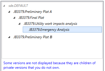
- Include a diagram to show the lineage of all versions you have created in the geodatabase so far.
- Place all requirements in a Word Document, and submit it to the dropbox on BBLearn.
Application 1:
Some utility maintenance work was scheduled for a water main segment on West High Country Trail (top part of the map) between 10:00 am and 4:00 pm. Junctions 19607 and 9181 will be shut off during the hours of utility work.
Create a version named Utility work impacts analysis based on your Final Plat version and perform an impact analysis to show areas that will be affected by the scheduled utility work in this version. The impact analysis results will be used to notify residents in the affected area in advance.
Notes
- To shut off a segment of the pipeline for maintenance, set the Enabled property of the two end junctions to False.
- Uninitialized flow symbols indicate no water supply or isolated subnet.
- Indeterminate flow symbols indicate uncertain flow direction but water supply is on.
- You do not have to identify individual parcels possibly affected by the utility work in this project. However, you may be requested to do so in in a real job. Think about how you would create a list of names and mailing addresses of home owners in GIS (up to 5 points of bonus for a complete solution. Submit a report including procedure, resulting mailing list, and a map etc. in MS-Word document to the instructor by BbLearn email).
Application 2:
During the utility work, an emergency was reported that a pipeline burst near the bike trail between South Nicholas Street and South Wild West Trail. The GIS technician at the utility department quickly identified the failed pipeline segment (FacilityID = 230929623) and created a version named Emergency analysis based on the Utility work impacts analysis version to find water outage areas caused by both events - the scheduled utility work and the emergency.
Tip: The FacilityID is a water line.
Lab 7 Extra Credit – Creating a mailing list of properties impacted by a utility work
In a utility network, a section of the network is isolated by turning off junctions at all of its entrances, creating a subnet. Elements of this isolated subnet can be identified and selected by the Find Connected function of the Utility network analyst.
If a utility network contains service laterals going into every property, a parcel intersected by a selected service lateral can then be selected. However, our utility network does not have service laterals leading to every parcel. We could use Select By Proximity (within 60 feet) to select parcels from selected water mains. The key is getting the parcels selected. Once selected, we can extract owner names and mailing addresses by selecting by attribute.
Here's how to do it:
- Ensure you have isolated the utility work area by disabling both end junctions of the pipeline.
-
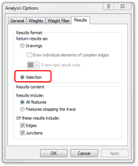
On the Utility Network Analyst toolbar, click Analysis | Options to open the
analysis options dialog. In the results format tab, select return results as
Selection. Click OK to close the dialog. This setting will cause the results of the network analysis in the next step to be selected.
-
To select all waterline elements in the utility work area, choose the Add Edge Flag Tool, then click on any waterline segment (edge) in
the utility work area.
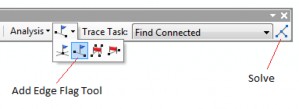
- In the trace tasks list, select the Find Connected function and click the Solve button. All utility network elements including water lines and junctions in the isolated subnet should now be selected.
-
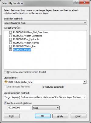
With the water lines in the isolated subnet now selected, you can use them to select parcels by spatial proximity. To do so, click on
Select By Location. See the screenshot below to setup selection parameters.
-
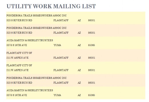
Once the adjacent parcels are selected, open the parcels attribute table. Click Table Options | Reports | Create Report Wizard:
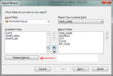
- Select the following fields OWN_NAME, ADDRESS, CITY, STATE, ZIP_CODE from the available fields box (left) and move them into the report field box (right).
- Click the Dataset Options button and select Selected Set to report selected records only. Click OK, then Finish.
- ArcMap should generate a report looking something like this: